First Project with ABB Control Builder
First Project with ABB Control Builder

In today's practice, we will see how to create a project for an ABB PLC. This will be the first time I use this software, so I will detail all the steps.
I couldn't start without thanking Linkinx64 for all their recommendations for working with ABB. Thank you so much for your help and recommendation.
The software we will use is PS501 Control Builder Plus, based on CodeSys.
We run our program and the first thing we do is create a new project; the program interface is as follows:

When creating a new project, the first thing we need to configure is the hardware of our equipment; here it will be fictitious as we will see how to use the simulator to test our programs.
We select our CPU and then we will add the additional modules.

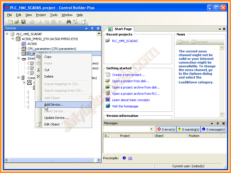
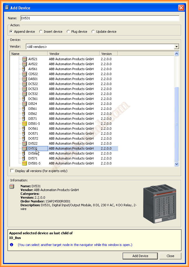
In the project tree, below the CPU, we have IO_Bus where we will select to add the different input/output modules, etc... a new window will open where we can select them.

The next thing we will do is assign the corresponding symbols to the inputs and outputs; it is highly recommended to do this as when we edit with CodeSys, all of them will be imported as Global variables to be used in our program.


Once all the symbols are created, and after modifying everything related to the hardware such as the IP address, we can now edit our program; to do this, we proceed as follows:

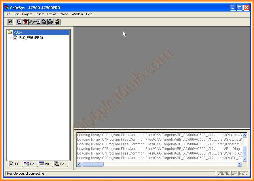
At the same time, the CodeSys software opens and by default in the POUs tab, here is where we will add our subroutines, functions, etc... and from where in the PLC_PRG (PRG) main program, we will call the different blocks created.
If we switch to the Resources tab, we can see the directory of several folders containing libraries with functions already prepared to be instantiated.
Within Global Variables, IO_Bus we have all the inputs and outputs that we created, and as it is said, they are global scope variables, to be used anywhere in the program.

We return to the POUs tab and add a new program and choose the programming language to be used; since it will be a small functionality test, we add the check of whether we have an input activated, we will activate an output, otherwise we will not.

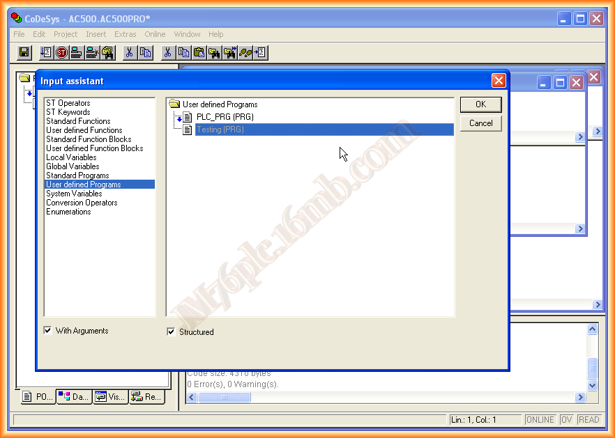
The next thing we will do is call our program from PLC_PRG (PRG); we open it and to call it we can use the wizard.

Once we have added it, we can compile and check the results; if we have no errors, we can proceed to simulate it or, alternatively, transfer it to our PLC.
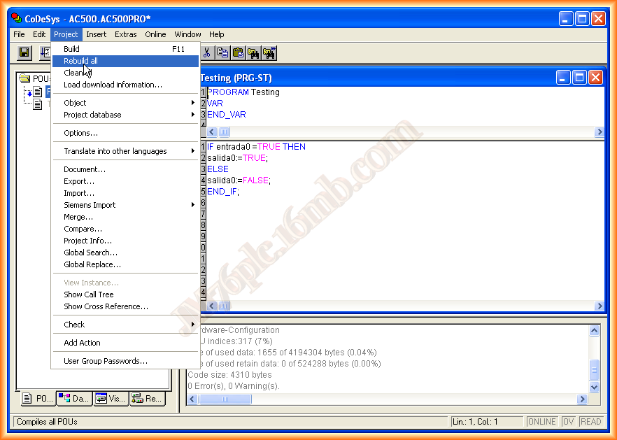
To start the Simulation mode, we go to Online and activate Simulation Mode.
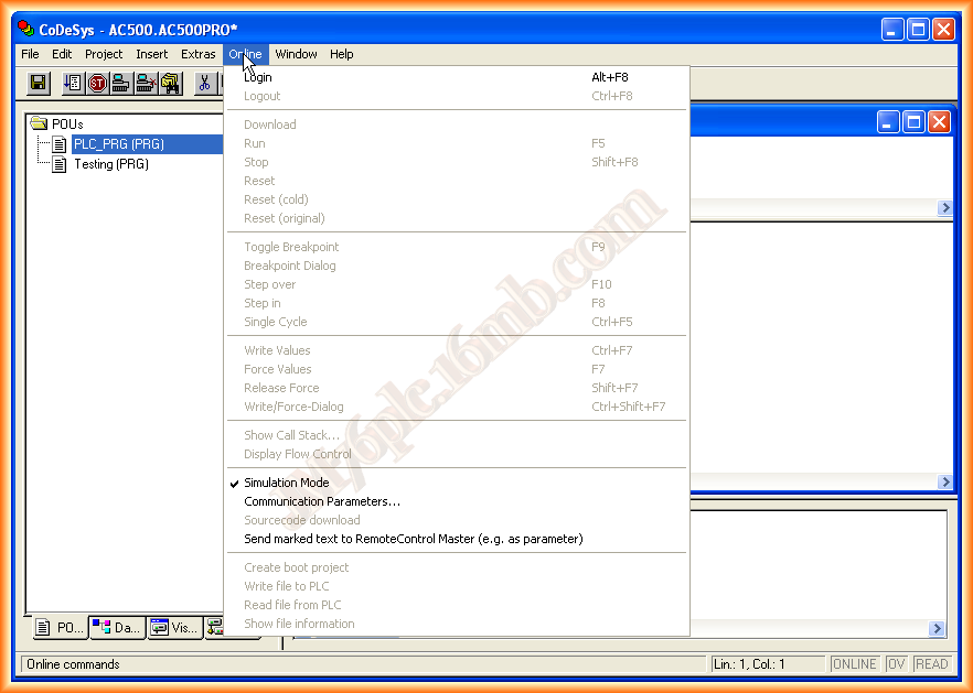
Once we are in simulation mode, still in Online, we log in; this is equivalent to establishing communication with the PLC.
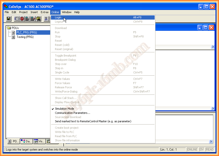
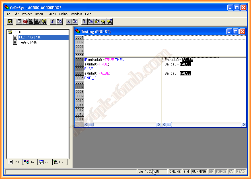
Upon logging in, we are now connected to the PLC, so we can see at the bottom that simulation mode appears and that we are Online.

Finally, we execute Run to start the program, and we are now enabled to force and change our variables.

To change the state of a variable, we click on it, and once the desired value is selected, we return to Online and force the assigned value.

With this, we are ready to perform some function and check its operation; to exit simulation mode, we follow the same steps but in reverse, that is, first we do STOP -> LOGOUT -> and deselect the Simulation Mode option.
January 25, 2013